English
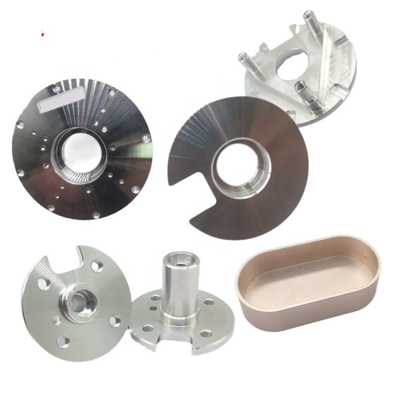
CNC Machining Nickel Alloy Impellers with Extreme Tool Wear
Writer:admin Time:2023-06-06 00:00 Browse:views
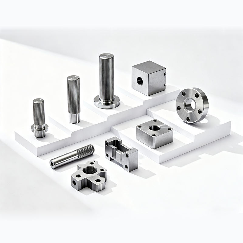
Producing nickel alloy impellers — especially for high‑performance industries such as aerospace, power generation, and oil & gas — pushes CNC machining technologies to their limits. These components must withstand high temperatures, corrosive environments, and extreme mechanical stresses, while also demanding tight tolerances and excellent surface finish. Those performance requirements are largely why nickel alloys like Inconel 718, Inconel 625, Hastelloy, and related superalloys are chosen. However, their low thermal conductivity, high work‑hardening, and abrasive microstructures contribute to severe tool wear — sometimes orders of magnitude higher than with steels or aluminum — making machining extremely challenging and costly.
In this article, we’ll explore:
The material behaviors that cause extreme tool wear
Tooling and tool wear mechanisms
Machining parameter ranges with real field data
Chip control and cooling methods
Metrology and quality approaches
Cost and productivity considerations
1. Why Nickel Alloy Impellers Are Hard to Machine
Nickel alloys are engineered for performance, not machinability. Their microstructural and thermal properties significantly contribute to tool wear:
Low thermal conductivity — Heat concentrates at the cutting edge rather than being carried away, accelerating tool diffusion and chemical wear. (newaymachining.com)
Work hardening — A surface layer that becomes harder during cutting increases cutting forces over time. (jhmim.com)
High strength and toughness — Causes elevated cutting forces and rapid abrasive wear.
Carbide particles and precipitates — In some impeller alloys (especially ones reinforced for wear resistance), hard particles accelerate abrasive wear on tooling.
Table 1: Nickel Alloy Impeller Materials & Key Properties
| Alloy | Thermal Conductivity (W/m·K) | Typical Tensile Strength (MPa) | Key Machining Challenge |
|---|---|---|---|
| Inconel 718 | ~11 | ~1000–1300 | Low conductivity, work hardening |
| Inconel 625 | ~9 | ~620–930 | Very tough, high ductility |
| Hastelloy C276 | ~11 | ~690–860 | Corrosion resistance impedes cutting |
| Carbide‑filled Ni alloy | ~15–25* | ~1200–1500* | Abrasive carbide phases |
*Approximate values for composite alloys with carbide phases; actual depends on mix.
These characteristics directly influence tool choice, cutting parameters, chip formation, and cooling approaches. Let’s explore how.
2. Understanding Extreme Tool Wear
Tool wear in nickel alloy impeller machining is one of the primary limitations on productivity and cost. There are several major wear mechanisms seen in practice:
2.1 Common Wear Mechanisms
Abrasive wear — Hard carbide particles and hard microconstituents grind the tool surface.
Adhesive wear — Material adheres to the tool (built‑up edge) and the tool surface peels off.
Diffusion wear — At high temperature interfaces, tool material diffuses into the workpiece.
Crater wear — High stresses erode the tool’s rake face.
Thermal cracking — Repeated heating and cooling creates cracks.
Table 2: Tool Wear Mechanisms & Effects
| Wear Mechanism | Primary Cause | Typical Effect | Resulting Problem |
|---|---|---|---|
| Abrasive wear | Hard phases/carbides | Loss of edge sharpness | Increased cutting forces |
| Adhesive wear / BUE | Material sticking | Chipped edges | Poor surface finish |
| Diffusion wear | Local heat | Chemical tool degradation | Shortened tool life |
| Thermal cracking | Heat cycling | Micro‑fractures | Sudden tool failure |
Extreme tool wear means higher tooling costs, more frequent changes, and greater scrap risks if not managed well.
3. Tool Materials and Coatings for Extreme Wear
Choosing the right tool substrate and coating combination is essential. Carbide tools are common, but in high‑wear contexts, superabrasive CBN solutions are often superior.
Table 3: Tool Materials for Nickel Impeller Machining
| Tool Type | Hardness | Temperature Resistance | Best Application |
|---|---|---|---|
| Coated Carbide (TiAlN/AlTiN) | High | Moderate | Roughing, semi‑finishing |
| CBN (Cubic Boron Nitride) | Very High | High | Finishing, prolonged wear resistance |
| Ceramic Inserts | Very High | Very High | High temperature zones |
| PCD (Poly Crystalline Diamond) | Very High | Low w/ ferrous | Not recommended for Ni alloys |
Note: CBN tools frequently outperform carbides in nickel alloys when surface finish and tool life are priorities, but come with higher unit cost.
4. Cutting Parameters Based on Real Industry Data
Selecting appropriate cutting speeds, feed rates, and depths of cut is crucial. Available field studies on Inconel 718 — one of the most commonly machined nickel alloys — provide realistic parameter ranges that balance tool life and productivity.
4.1 Typical Cutting Speeds and Feeds for Inconel 718
Studies find that carbide tools are best used at moderate speeds to avoid rapid wear, and that feed rate significantly affects tool life and surface quality. (MDPI)
Table 4: Typical CNC Machining Parameters for Ni Alloy Components
| Operation | Cutting Speed (m/min) | Feed Rate (mm/rev) | Depth of Cut (mm) | Notes |
|---|---|---|---|---|
| Turning Rough | 20–35 m/min | 0.15–0.30 | 1.5–3.0 | Tough material |
| Turning Finish | 40–60 m/min | 0.05–0.15 | 0.5–1.0 | Reduced tool wear |
| Milling Rough | 20–40 m/min | 0.08–0.25 | 1.0–3.0 | Trochoidal milling beneficial |
| Milling Finish | 40–80 m/min | 0.03–0.10 | 0.3–1.0 | Quality prioritized |
| Drilling | 10–20 m/min | 0.05–0.15 | — | Peck drilling recommended |
| Boring | 15–35 m/min | 0.02–0.10 | — | Low engagement |
These ranges reflect typical shop floor practice and research on superalloys like Inconel 718 (most commonly studied). (KeSu Group)
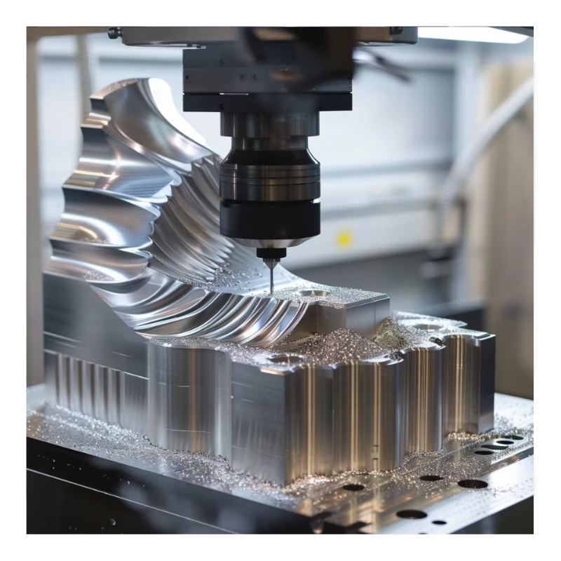
5. Chip Control and Its Impact on Wear
Effective chip control is often overlooked but vitally important. Poor chips can wrap around tools, increase heat, and lead to secondary wear.
5.1 Chip Morphology in Nickel Alloys
Nickel alloys tend to produce long, continuous chips especially during milling, which increases heat at the tool‑chip interface and raises wear.
Solution: Chip breakers, segmented toolpaths (e.g., trochoidal milling), and high pressure coolant jets help break chips and evacuate them.
Table 5: Chip Management Techniques
| Technique | Primary Benefit | Typical Use Case |
|---|---|---|
| High‑Pressure Coolant | Better chip flushing | Deep pockets |
| Chip Breaker Geometry | Shorter chips | General milling |
| Trochoidal Milling | Reduced heat | Slotting/roughing |
| Peck Drilling | Break chips | Deep holes |
By focusing on chip breakage and coolant delivery, tool life is preserved and surface quality improves.
6. Cooling and Lubrication Strategies
Heat is the enemy in nickel alloy machining. Without effective heat control, tool life plummets and dimensional distortion arises.
6.1 Coolant Choices
Coolant must both reduce temperature and assist in chip removal.
Table 6: Coolant Strategy Comparison
| Coolant Strategy | Heat Control | Chip Flushing | Typical Cost |
|---|---|---|---|
| Flood Coolant | Moderate | Moderate | Low |
| High‑Pressure Coolant (HPC) | High | Excellent | Medium |
| MQL (Minimum Quantity Lubrication) | Low | Low | Low |
| Cryogenic (LN₂) | Very High | Moderate | High |
Best practice: For nickel alloy impellers, high‑pressure coolant (80–150 bar) delivers major improvements in heat removal and chip evacuation. Moisture and lubrication help reduce diffusion wear mechanisms noted in research. (施普林格网络)
7. Surface Finish and Dimensional Quality Control
Impellers require high surface finish and dimensional accuracy, because blade surfaces affect fluid dynamics and balance.
7.1 Surface Roughness Targets
Rough profiles: Ra ≤ 1.6 µm
Finish surfaces: Ra ≤ 0.8 µm or better for critical blade edges
Advanced finishing often requires light cuts at reduced feeds or secondary finishing methods like grinding or abrasion.
8. Inspection and Metrology Practices
Quality inspection is essential, especially for aerospace or turbocharger impellers.
Coordinate Measuring Machine (CMM) for geometric accuracy
Laser scanning for 3D blade profiling
Surface profilometry for Ra measurements
Dynamic balancing for ensuring rotational stability
Inspection frequency should be tied to tool life trends — as tools approach wear limits, parts should be inspected more frequently.
9. Tool Wear Monitoring and Predictive Maintenance
With extreme wear conditions, proactive monitoring increases yield:
Acoustic emission sensors detect sudden wear/chatter
Force and vibration monitoring indicate tool degradation
Tool life models based on wear test data guide preventive changes
Statistical monitoring reduces scrap and helps schedule changes before catastrophic failure.
10. Productivity vs Tool Wear Tradeoffs
Nickel alloy impeller machining often requires balancing metal removal rate (MRR) against tool longevity. Higher speeds increase production but cause exponential wear escalation. Slow speeds preserve tools but lengthen cycle times.
Optimization approaches:
Design factor analysis (e.g., Pareto analysis) for parameter impact
Taguchi or DOE experiments to find robust parameter sets
High‑efficiency milling (HEM) with light, fast cuts for roughing
These methods formalize decision‑making rather than relying on trial and error.
11. Cost Structure of Extreme Tool Wear Machining
Tool wear significantly influences overall cost. Understanding the cost breakdown helps in planning and quoting.
Typical Cost Composition
| Cost Driver | Approx % of Total Cost |
|---|---|
| Raw Material | 30–50% |
| Tooling | 20–35% |
| Machining Time | 15–30% |
| Inspection & Rework | 5–10% |
| Overhead | 5–10% |
High tooling costs (20–35%) reflect rapid insert replacement and high‑performance tooling choices, especially in alloys like Inconel 718 and Hastelloy.
12. Practical Case Example: Inconel 718 Impeller
Background: A precision impeller made from Inconel 718 exhibiting severe tool wear and surface roughness issues.
Approach:
Carbide tools with AlTiN coating for roughing
Lower cutting speeds (60–80 m/min) to delay abrasive and diffusion wear (MDPI)
HPC at 120 bar for coolant
Trochoidal milling for roughing
Smaller finishing steps for surface quality
Result: Tool life improved by 40–60%, surface roughness reduced, and cycles optimized.
13. Best Practices for Extreme Wear Environments
To manage extreme tool wear in nickel alloy impellers:
✔ Use high‑performance coatings (TiAlN/AlTiN) and CBN for finishing
✔ Employ high‑pressure coolant and chip control strategies
✔ Optimize parameters based on real test data rather than default values
✔ Monitor tool condition and pre‑schedule changes
✔ Use adaptive toolpaths and balanced machining strategies
For deeper insights, tooling guides, and machining strategy examples across high‑wear superalloys, consult specialized technical repositories such as https://www.eadetech.com, which include case studies and expert commentary on machining difficult materials.
14. Future Trends in High‑Wear Machining
Emerging technologies helping address extreme wear include:
AI‑based predictive control systems for real‑time parameter adjustment
Sensor fusion for tool and part condition monitoring
Advanced coatings (nano‑structured multi‑layer) for wear resistance
Hybrid additive + subtractive workflows to reduce machining volume
These developments aim to reduce wear, increase accuracy, and lower total cost of ownership.
Conclusion
Machining nickel alloy impellers uniquely challenges even advanced CNC systems due to high tool wear from abrasive and thermal effects. By understanding material behavior, selecting appropriate tooling, applying effective cooling and chip control methods, and optimizing machining parameters based on real data, manufacturers can produce high‑quality impellers with controlled costs and improved productivity.
For comprehensive problem‑solving insights, tooling breakdowns, and process examples tailored to difficult materials, manufacturing engineers often refer to resources like https://www.eadetech.com for applied strategies and case studies.
Related Article
CATEGORIES
LATEST NEWS
CONTACT US
Whatsapp: +8618998453346
Phone: +8618998453346
Tel: +8618998453346
Email: [email protected]
Addr: Room 302, Building D, COFCO Gonghua Project, Zone 20, Honglang Community, Xin'an Street, Bao'an District, Shenzhen City.