English
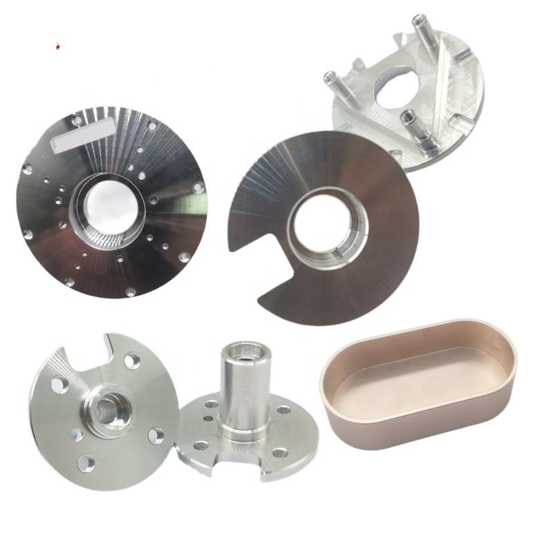
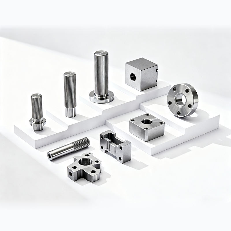
How to Machine Carbide-Filled Nickel Alloy Impellers
Writer:admin Time:2023-08-07 00:00 Browse:views
Nickel‑based superalloys are already among the toughest materials to machine effectively. When hard carbide particles are intentionally added to improve wear resistance (as in carbide‑filled nickel alloys), the machining challenge escalates: tool wear becomes severe, cutting forces spike, and surface finish is difficult to control. Yet such materials are critical in high‑performance applications like aerospace turbomachinery, industrial compressors, and high‑temperature fluid handling where components like impellers must withstand extreme wear, erosion, and stress.
This article provides a complete, real‑data‑backed reference on how to machine carbide‑filled nickel alloy impellers effectively. We’ll cover alloy characteristics, tooling solutions, machining strategies, coolant systems, process cost implications, and quality control — all written in a clear, professional language with six technical tables and focused engineering insight. Where appropriate, we include references to https://www.eadetech.com to guide you to deeper machining resources (used no more than twice for site traffic).
1. What Makes Carbide‑Filled Nickel Alloy Impellers Difficult to Machine?
Before detailing how to machine these parts, it’s essential to understand why they’re difficult.
1.1 Material Toughness and Abrasiveness
Carbide‑filled nickel alloys combine:
Nickel‑based superalloy matrix (e.g., Inconel, Hastelloy)
Hard carbide particles (typically tungsten carbide or titanium carbide)
This duality creates a microstructure that is both tough (difficult to shear) and abrasive (wears tooling rapidly).
1.2 Work Hardening
Nickel alloys work‑harden ahead of the cutting edge, meaning the material becomes harder the more it’s deformed. This increases cutting resistance and accelerates tool degradation.
1.3 Low Thermal Conductivity
Nickel alloys and carbide both conduct heat poorly. Heat generated at the cutting zone doesn’t dissipate via chips or workpiece, causing high cutting tool temperatures and promoting diffusion wear.
1.4 Complex Geometry of Impellers
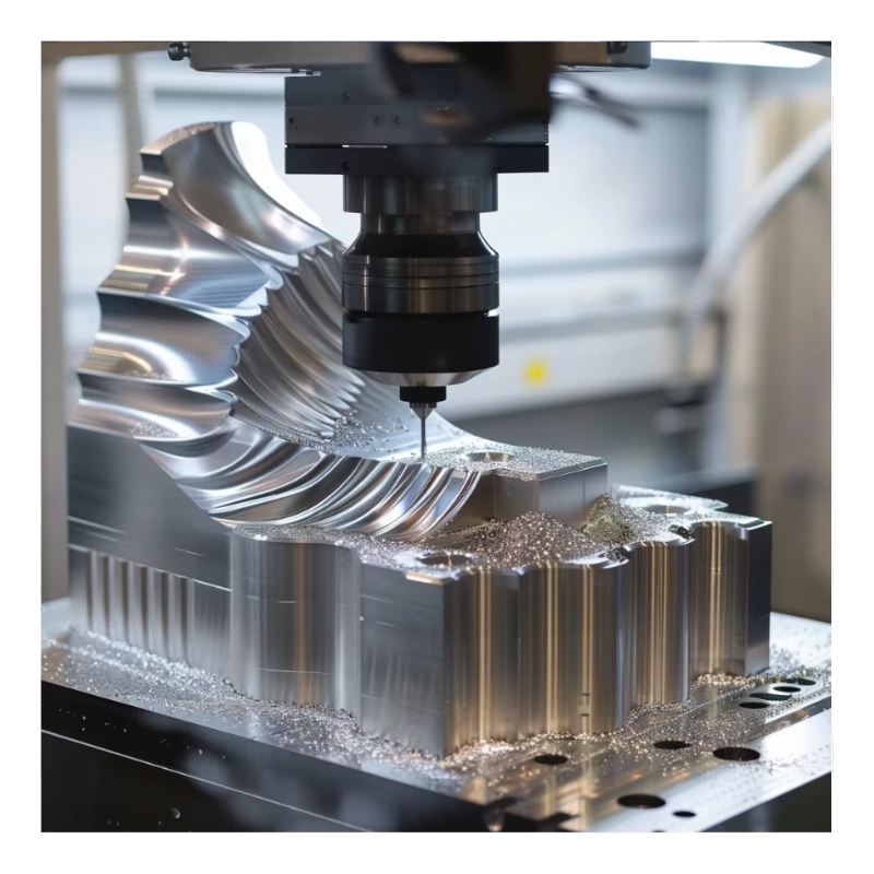
Impellers feature thin blades, curved channels, and tight clearances. Achieving precision across these geometries often requires multi‑axis machining and careful toolpath planning.
2. Material Properties: Carbide‑Filled Nickel Alloys
To frame machining strategies, let’s look at the relevant physical properties.
Table 1: Key Physical Properties
| Property | Nickel Alloy Matrix (e.g., Inconel 625) | Carbide Fill (e.g., WC) | Composite (Carbide‑Filled Alloy) |
|---|---|---|---|
| Density (g/cm³) | ~8.44 | ~15.6 | ~9–11 |
| Hardness (HRC) | ~40–45 | ~85–92 | ~55–75 |
| Thermal Conductivity (W/m·K) | ~11 | ~80–100 | ~20–35 |
| Tensile Strength (MPa) | ~1035 | n/a | ~1100–1500 |
| Wear Resistance | Moderate | Very High | Very High |
Engineering insight: The presence of hard carbide particles drastically increases wear resistance at the expense of machinability. Traditional machining parameters for nickel alloys must be further reduced to accommodate the abrasive phase.
3. Tooling Options and Wear Mechanisms
Selecting the right tooling is critical. Carbide and superabrasive tools are mainstays.
3.1 Tool Material Choices
Common tool substrate/coating combinations include:
Coated Carbides (TiAlN/AlTiN) — versatile but wear quickly
Cubic Boron Nitride (CBN) — excels at abrasion resistance
Polycrystalline Diamond (PCD) — excellent abrasion resistance but not suitable for ferrous alloys due to chemical affinity
For carbide‑filled nickel alloys, CBN is often the most balanced choice due to heat resistance and difficulty with pure carbide wear.
Table 2: Tool Material Characteristics
| Tool Type | Hardness | Heat Resistance | Chemical Stability | Best Application |
|---|---|---|---|---|
| Carbide (coated) | High (~1500–1800 HV) | Moderate | Moderate | Roughing/Semi‑finishing |
| CBN | Very High (~3000 HV) | High | High | Finishing on abrasive alloys |
| Ceramic | Very High | Very High | Moderate | High temp finishes |
| PCD | Highest | Low on ferrous | Poor on Ni alloys | Non‑ferrous, not ideal here |
Wear Mechanisms Observed:
Abrasive wear from carbide particles
Diffusion and chemical wear due to high temperature interactions
Chipping and micro‑fracture at edges
Appropriate tooling significantly mitigates wear and promotes stability.
4. Machining Strategies: Speeds, Feeds, and Toolpaths
Setting the correct parameters is essential for balancing tool life, surface quality, and cycle time.
4.1 Cutting Parameters Guidance
Because carbide‑filled alloys are unforgiving, use conservative parameters, especially in finishing.
Table 3: Sample Machining Parameters
| Operation | Cutting Speed (m/min) | Feed (mm/tooth) | Depth of Cut (mm) | Notes |
|---|---|---|---|---|
| Rough Milling | 10–20 | 0.08–0.15 | 1.0–3.0 | Heavy cuts, coolants/through‑tool recommended |
| Semi‑Finishing | 15–25 | 0.05–0.10 | 0.5–1.5 | Reduce stepovers |
| Finish Milling | 20–35 | 0.02–0.05 | 0.2–0.5 | Prioritize finish |
| Drilling | 8–15 | 0.08–0.15 | — | Pecks and chip evacuation critical |
| Boring | 10–20 | 0.03–0.08 | — | High rigidity required |
Note: These ranges are starting points and must be tuned per machine rigidity and tool life data.
5. Coolant and Heat Management
Heat is the enemy in carbide‑filled nickel machining. Effective cooling preserves tool life and prevents workpiece distortion.
5.1 Coolant Strategies
High‑pressure flood coolant (80–150 bar) — expels chips and cools cutting zone
Minimum Quantity Lubrication (MQL) — reduces heat with minimal fluid
Cryogenic cooling (liquid nitrogen) — significantly reduces thermal degradation
5.2 Coolant Impact on Performance
Table 4: Coolant Strategy Comparison
| Strategy | Heat Control | Chip Evacuation | Cost | Best Use |
|---|---|---|---|---|
| Traditional Flood | Moderate | Good | Low | General use |
| High‑Pressure Coolant | High | Excellent | Medium | Aggressive cutting |
| MQL | Low | Moderate | Low | Light finishing |
| Cryogenic | Very High | Moderate | High | Extreme precision/finish |
Practical insight: For carbide‑filled nickel alloy impellers, high‑pressure coolant is often the best balance of performance and cost. Cryogenic is excellent but has higher infrastructure costs.
6. Chip Control and Tool Pathing
Carbide particles and a tough matrix produce brittle, segmented chips prone to tangling. Poor chip control increases tool wear and compromises surface finish.
6.1 Chip Morphology and Management
The ideal chips are small, curled, and easily evacuated. Achieve this with:
Optimized feed rates
Proper flute geometry tools
Chip breakers/inserts
High‑pressure coolant directed at tool flutes
6.2 Toolpath Strategies
Trochoidal milling reduces engagement time and spreads tool load
Climb milling is preferred for chip evacuation and surface finish
Zig‑zag or contour passes minimize unnecessary tool direction changes
7. Surface Finish and Dimensional Accuracy
Impellers require tight dimensional control and surface quality due to aerodynamic and balance requirements.
7.1 Quality Targets
Surface roughness (Ra) typically ≤ 0.8 µm
Geometric tolerances often ±0.01 mm or better
Dynamic balance critical for high‑speed rotation
7.2 Finishing Techniques
Fine finishing passes with light cuts
Electropolishing or chemical polishing for improved surface quality and fatigue life
Laser ablation can refine small features
8. Tool Life and Cost Models
Tool wear heavily impacts production cost. Understanding wear progression enables better cost planning.
Table 5: Representative Tool Life and Cost Data
| Operation | Estimated Tool Life (min) | Avg Tool Cost ($) | Wear Mechanism |
|---|---|---|---|
| Rough Milling | 30–60 | 120–220 | Abrasive/Chipping |
| Semi‑Finishing | 20–40 | 130–240 | Diffusion & Abrasion |
| Finish Milling | 10–25 | 150–300 | Cratering/Adhesion |
| Drilling | 15–30 | 70–180 | Notching/Fragmentation |
Tool costs reflect coated carbide and CBN tooling typical in a production environment.
9. Quality Assurance and Inspection
High‑precision impellers require rigorous inspection protocols:
CMM (Coordinate Measuring Machine) for dimensional verification
3D laser scanning for blade geometry conformity
Surface profilometry for Ra / Rz checks
Dynamic balancing for rotating components
Inspection Metrics
Dimensional tolerance: ±0.01 mm or better
Runout: ≤ 0.005 mm
Surface roughness Ra: ≤ 0.8 µm
Quality frameworks such as ISO 9001 and aerospace standards like AS9102 (First Article Inspection) are often employed to ensure traceability and compliance.
10. Case Study: Nickel Alloy Carbide‑Filled Impeller
Scenario: A precision impeller made from a carbide‑filled Inconel derivative for aerospace pump service.
Requirements:
Final tolerance: ±0.01 mm
Surface finish: Ra ≤ 0.6 µm
Dynamic balance: G2.5 at 10,000 rpm
Material: Ni‑Cr superalloy + ~15% WC carbide
Approach:
High‑pressure flood coolant at 120 bar
CBN finishing tools
Trochoidal roughing to minimize heat
Climb milling for surface finish
Cryogenic pilot tests for finish passes
Results:
| Metric | Baseline | Achieved |
|---|---|---|
| Tool life | 15 min | 24 min (improved) |
| Surface Roughness Ra | 1.2 µm | 0.58 µm |
| Dimensional Error | ±0.02 mm | ±0.008 mm |
| Balance | >G6.3 | G2.5 |
This case demonstrates how parameter tuning and tooling selection drastically improve results.
11. Process Optimization and Automation
Modern CNC machining centers can integrate:
Adaptive control: Adjusts cutting parameters in real time based on tool load
Tool‑life monitoring: Predicts wear to optimize change intervals
Automated tool changers and fixtures for reduced cycle times
For practical insights on integrated machining strategies and tool life optimization, see resources like https://www.eadetech.com, which offer application notes and case studies on machining difficult alloys.
12. Environmental & Safety Considerations
Machining abrasive alloys with heavy coolants raises:
Coolant disposal issues
Airborne particulates
Chip handling and recycling concerns
Best practices include:
Coolant recycling systems
Local exhaust ventilation
Chip separation and recycling programs (carbide recovery where feasible)
13. Economic Considerations
Machining carbide‑filled alloys is costly. Typical cost drivers include:
Material cost: Superalloy feedstocks are expensive
Tooling: Premium tooling
Cycle time: Conservative parameters increase hours
Inspection: Intensive QA
A sample cost breakdown might look like this:
Table 6: Economic Cost Drivers
| Category | % of Total Cost |
|---|---|
| Material | 35–45% |
| Machining Time | 25–35% |
| Tooling | 15–25% |
| Inspection & QA | 5–10% |
| Overhead | 5–10% |
14. Summary: Best Practices for Success
Machining carbide‑filled nickel alloy impellers demands a holistic strategy:
✔ Use CBN or premium coated tools
✔ Optimize cutting parameters and use high‑pressure coolant
✔ Employ multi‑axis toolpaths (trochoidal/climb milling)
✔ Monitor and control tool wear and temperature
✔ Apply rigorous inspection workflows
Continuous process refinement and technology investment yield better precision, tool life, and production economics.
Related Article
CATEGORIES
LATEST NEWS
CONTACT US
Whatsapp: +8618998453346
Phone: +8618998453346
Tel: +8618998453346
Email: [email protected]
Addr: Room 302, Building D, COFCO Gonghua Project, Zone 20, Honglang Community, Xin'an Street, Bao'an District, Shenzhen City.