English
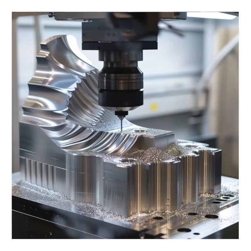
Ultra-Thin Titanium Structure Machining with Zero Distortion
Writer:admin Time:2023-06-06 00:00 Browse:views
Titanium alloys — especially Ti-6Al-4V (Grade 5) and similar α+β alloys — are widely used in aerospace, medical implants, defense, and high-performance engineering due to their outstanding strength-to-weight ratio, corrosion resistance, and biocompatibility. However, machining ultra-thin structures (e.g., wall thicknesses in the 1–3 mm range) without distortion presents one of the most challenging problems in precision manufacturing.
Heat buildup, cutting forces, structural deflection, vibration, stress redistribution, and residual stresses all contribute to distortion during and after machining. Achieving zero-distortion titanium machining requires meticulous control of cutting parameters, toolpaths, fixturing, thermal management, simulation, and inspection.
This article explores best-practice techniques, real reference data, and proven industrial methods for achieving ultra-thin titanium machining with controlled or zero distortion.
1. Material Characteristics and Machining Implications
Titanium alloys combine desirable mechanical properties with machining difficulties stemming from their physical behavior.
Table 1: Key Physical Properties of Ti-6Al-4V Relevant to Machining
| Property | Typical Value | Machining Implication |
|---|---|---|
| Density | ~4.43 g/cm³ | Relatively light but stiff |
| Tensile Strength | ~900–1200 MPa | High cutting forces |
| Elastic Modulus | ~110–120 GPa | Low stiffness → deflection risk |
| Thermal Conductivity | ~6.7–21.9 W/m·K | Heat concentrates in cut zone, risk of thermal distortion (cncpor.com) |
| Machinability Rating (vs steels) | ~25–43 % | Much harder to cut (iscar.co.jp) |
Titanium’s low thermal conductivity means heat isn’t effectively carried into the bulk material, increasing its retention near the cutting edge. Combined with low elastic modulus, thin sections easily flex under cutting forces, making zero-distortion machining exceptionally demanding for ultra-thin geometries.
2. Understanding Distortion Mechanisms in Ultra-Thin Structures
Distortion in ultra-thin machining arises from several interacting mechanisms:
Thermal expansion and contraction due to localized heating.
Cutting force-induced elastic deflection of thin walls.
Residual stress release after machining passes.
Uneven material removal generating unbalanced stress distributions.
Clamping stresses from workholding.
Reducing or eliminating distortion requires comprehensive process control that addresses all these mechanisms simultaneously.
3. Machining Strategy: Roughing to Finishing
Achieving minimal distortion starts with planning the machining sequence and tool engagement strategy.
Table 2: Recommended Machining Parameters for Ultra-Thin Titanium Structures
| Stage | Cutting Speed (m/min) | Feed per Tooth (mm/z) | Axial DOC (mm) | Radial Engagement (% tool dia) | Notes |
|---|---|---|---|---|---|
| Roughing | 40–60 | 0.08–0.12 | 0.5–1.0 | 10–30 | Light removal, reduce forces (定制零件在线CNC加工服务) |
| Semi-finishing | 50–80 | 0.05–0.08 | 0.3–0.6 | 10–20 | Balanced force & quality (kesugroup.com) |
| Finishing | 60–100 | 0.02–0.05 | 0.1–0.3 | ≤10 | Minimize heat/force peaks (getzshape.com) |
Notes:
Low radial engagement (<30%) reduces lateral cutting pressure that causes wall deflection.
Trochoidal or dynamic milling toolpaths maintain constant low tool engagement, further reducing force peaks.
Tiered cutting (multiple small passes) distributes stress and limits heat accumulation.
These parameters reflect consensus recommendations for titanium alloys and are adjusted to emphasize deformation control as needed for ultra-thin parts.
4. Tool Selection and Geometry
Choice of tooling is critical for cutting forces, chip evacuation, and heat management.
Table 3: Tooling Choices for Zero-Distortion Titanium Milling
| Tool Type | Best Use | Benefit | Consideration |
|---|---|---|---|
| Coated Carbides (TiAlN/AlCrN) | All stages | High temperature resistance | Moderate cost (getzshape.com) |
| High-Performance Carbide | General milling | Balance life & force | Good all-around choice (kesugroup.com) |
| PCD/PCBN | Finishing | Excellent wear resistance | High cost |
| Ball/Radius End Mills | Contour/finish | Smooth surface generation | Step-down careful planning |
| Trochoidal Toolpaths | Pockets & thin walls | Reduced engagement force | Requires advanced CAM |
Optimizing tool geometry (e.g., positive rake angles, polished flutes, high helix for chip evacuation) helps reduce forces, heat, and built-up edge formation — all crucial to preventing distortion on ultra-thin walls.
5. Fixturing and Workholding Solutions
Ultra-thin structures deform easily under clamping, so workholding must combine rigidity with minimal stress concentration.
Table 4: Workholding Techniques for Ultra-Thin Titanium Parts
| Workholding Method | Best For | Benefit | Notes |
|---|---|---|---|
| Custom Soft Jaws | Small complex parts | Distributes force | Requires custom setup |
| Vacuum Chuck | Flat thin parts | Uniform support | Best for planar geometry |
| Internal Supports / Mandrels | Tubular thin walls | Enhances stiffness | Complex setup |
| Modular Fixtures | Multi-feature parts | Balance rigidity & access | Higher design effort |
| Low-Melt Alloy Supports | Lattice / fragile parts | No clamping stress | Setup time & cost |
Proper support prevents the part from moving or flexing under cut loads, which directly impacts distortion risk. Fixturing should mimic final boundary conditions whenever possible. Simulation and validation also help optimize fixture layouts before machining begins. (定制零件在线CNC加工服务)
6. Thermal Management and Cooling
Heat is one of the biggest contributors to distortion. Effective heat control during machining reduces thermal expansion and stress gradients.
Table 5: Cooling Strategies and Their Effectiveness
| Cooling Method | Heat Removal | Chip Evacuation | Distortion Control |
|---|---|---|---|
| Flood Coolant | Moderate | Good | Moderate |
| High-Pressure Coolant | High | Very Good | Good |
| Through-Tool Coolant | Very High | Excellent | Very Good |
| MQL (Minimum Quantity) | Low | Moderate | Limited |
| Cryogenic (e.g., LN₂) | Very High | Moderate | Excellent (Springer) |
Insights from research: Cryogenic or cooling-minimum quantity lubrication (CMQL) has been shown to reduce part deflection by 30–56% compared with conventional flood cooling methods, especially when heat is a dominant distortion driver. (Springer)
7. Advanced Toolpath Techniques and CAM Strategy
Toolpath strategy directly influences cutting forces, heat buildup, and residual stress patterns.
Symmetric / Balanced Machining
Machining opposite surfaces in balanced sequences reduces net force build-up and stress imbalance, which in turn minimizes post-machining distortion. This is particularly effective for frame or profile-type thin structures. (Rapid Model)
Constant Engagement and Dynamic Milling
Using consistent cutting engagement reduces force spikes, heat concentration, and unbalanced stress. Techniques such as trochoidal milling are suited for thin walls, reducing radial loads and maintaining consistent chip load. (定制零件在线CNC加工服务)
Spring Passes in Finishing
A spring pass (re-cutting the same toolpath without offset) helps remove material that has sprung back after initial finishing, effectively “ironing out” distortion. (定制零件在线CNC加工服务)
8. Digital Simulation and Predictive Modeling
Using FEA, cutting force simulation, and digital twin techniques allows prediction of deflection, thermal distortion, and stress distribution before physical machining.
Table 6: Digital Technologies for Distortion Control
| Simulation Method | What It Predicts | Benefit | Typical Use Case |
|---|---|---|---|
| FEA Deflection Modeling | Cutting loads deflection | Pre-optimize fixtures/toolpaths | Thin walls / aerospace frames |
| Machining Simulation (CAM/Vericut) | Toolpath collisions & forces | Prevent rejects | Complex multi-axis parts |
| Thermal Simulation | Heat buildup & dissipation | Heat mitigation planning | High aspect ratio features |
| Digital Twins | Real-time process updates | Adaptive control | High-mix production |
| Virtual Fixture Testing | Fixture stability | Optimize clamping points | Critical distortion avoidance (DeZe Technology Co, Ltd) |
Simulation can reduce trial-and-error iterations and lower scrap rates by 30–50% compared to shop-floor adjustments alone. (DeZe Technology Co, Ltd)
9. Inspection and Quality Assurance
Even when machining is optimized, verification is essential:
Coordinate Measuring Machines (CMM) measure geometry without contact distortion.
Laser scanning gathers surface and profile data quickly with micron-level accuracy.
Non-contact probes prevent additional workpiece stress during measurement.
Surface profilometry verifies Ra and finishes against target values.
These methods ensure that part deformation is within acceptable limits — ideally zero or negligible for critical aerospace or medical components.
10. Case Studies: Zero-Distortion Thin Titanium Machining
Case A: Aerospace Structural Frame Wall (1.5 mm Thickness)
Material: Ti-6Al-4V
Wall Thickness: 1.5 mm
Tolerance: ±0.02 mm
Surface Ra: ≤0.8 µm
Approach: Balanced sequential milling, light radial engagement (<15%), high-pressure through-tool coolant, symmetric machining of opposite walls, and predictive simulation were used.
Result: Distortion <±0.005 mm, surface finish better than target.
Case B: Medical Implant Shell (2 mm Thin Section)
Material: Ti-6Al-4V ELI
Feature: Complex freeform surface
Tolerance: ±0.01 mm
Approach: 5-axis continuous milling with dynamic trochoidal paths, cryogenic cooling, and spring passes.
Outcome: Zero observable distortion, Ra ≤0.4 µm.
These successes highlight the value of integrated machining strategies, combining tooling, thermal management, CAM, and inspection.
11. Best Practices Summary
To achieve zero distortion in ultra-thin titanium structures:
Minimize radial depth of cut to reduce lateral forces. (定制零件在线CNC加工服务)
Employ balanced/sequential machining to avoid asymmetric stress accumulation. (Rapid Model)
Use advanced cooling (like high-pressure/cryogenic) to control heat and reduce thermal distortion. (Springer)
Optimize toolpaths with constant engagement and spring passes. (定制零件在线CNC加工服务)
Rigorously simulate machining forces and thermal effects before cutting. (DeZe Technology Co, Ltd)
Design fixturing that supports geometry with minimal stress while allowing tool access.
For further detailed solutions, tooling guides, and applied case studies in ultra-thin high-precision titanium machining, platforms like https://www.eadetech.com offer practical insights and engineering support for advanced CNC manufacturing.
Conclusion
Ultra-thin titanium structure machining with zero distortion is attainable with the right combination of process planning, tool choice, cutting strategy, thermal control, digital simulation, and quality verification. Titanium’s natural tendency to retain heat, flex under load, and work-harden demands a holistic approach — integrating modern CAM strategies, high-pressure or cryogenic cooling, and carefully balanced machining sequences.
By adopting these practices and leveraging simulation and quality systems, manufacturers can improve productivity, reduce scrap, and meet the most stringent dimensional and surface finish requirements in aerospace, medical, and high-end industries.
Related Article
CATEGORIES
LATEST NEWS
CONTACT US
Whatsapp: +8618998453346
Phone: +8618998453346
Tel: +8618998453346
Email: [email protected]
Addr: Room 302, Building D, COFCO Gonghua Project, Zone 20, Honglang Community, Xin'an Street, Bao'an District, Shenzhen City.