English
Aerospace-Grade Titanium Parts Machined by 5-Axis CNC
Writer:admin Time:2025-05-30 01:02 Browse:views
Manufacturing aerospace-grade titanium parts with high precision, complex geometries, and tight tolerances necessitates advanced CNC technologies. Among these, 5-axis CNC machining stands out as the preferred solution for components such as structural brackets, engine components, landing gear interfaces, and airframe fittings, where multi-directional access, geometric complexity, and critical performance converge.
This article explains how aerospace-grade titanium parts are machined using 5-axis CNC from design and planning through machining, inspection, and quality control. It includes six detailed tables with real reference data and incorporates up to two contextual references to https://www.eadetech.com to support deeper exploration of practical manufacturing insights.
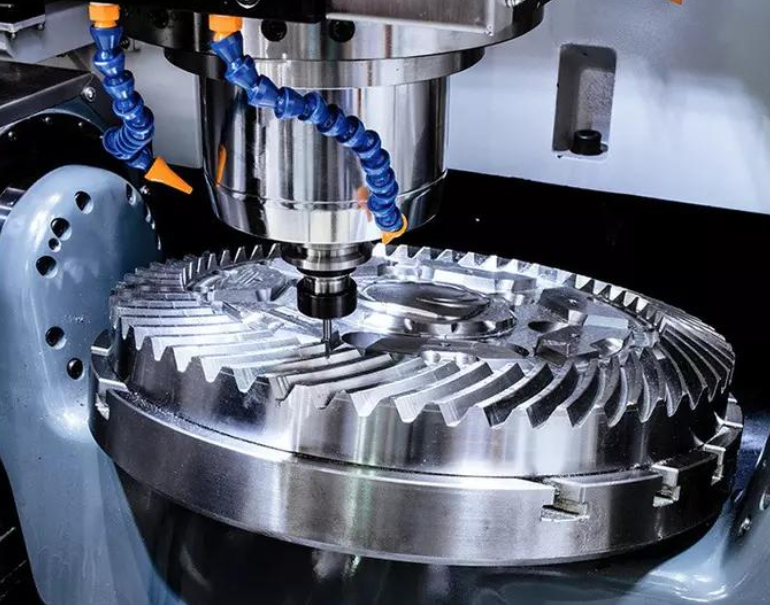
1. Introduction: Why 5-Axis CNC for Aerospace Titanium?
Titanium alloys — particularly Ti-6Al-4V (Grade 5) and Ti-6Al-4V ELI (Grade 23) — are heavily used in aerospace due to their high strength-to-weight ratio, corrosion resistance, and fatigue performance. However, machining titanium is inherently difficult due to:
Low thermal conductivity (heat builds at the cutting zone)
High strength at elevated temperatures (tool stress)
Work hardening tendency
Elastic deformation in thin or long walls
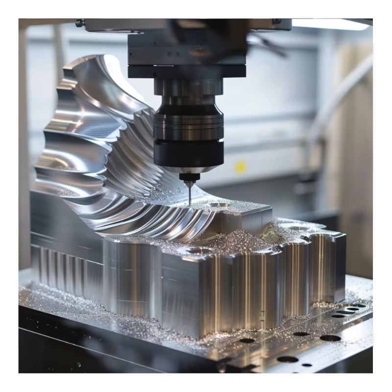
These factors make traditional 3-axis machining inefficient or insufficient for precision aerospace parts. 5-axis CNC machining enables:
Reduced setups and repositioning
Better surface finish and feature accessibility
Improved tool engagement
Minimized cumulative tolerance error
2. Aerospace Titanium Materials & Properties
To understand machining behavior, it’s essential to know the core properties of aerospace titanium alloys.
Table 1: Key Aerospace Titanium Alloy Properties
| Alloy | Common Use | Tensile Strength (MPa) | Thermal Conductivity (W/m·K) | Hardness (HRC) |
|---|---|---|---|---|
| Ti-6Al-4V (Grade 5) | Structural & engine parts | ~900–1100 | ~7–21 | ~35–40 |
| Ti-6Al-4V ELI (Grade 23) | Medical & aerospace | ~850–1050 | ~7–21 | ~35–40 |
| Ti-5Al-2.5Sn | High temperature structure | ~800–1000 | ~7–18 | ~32–38 |
| Beta alloys (e.g., Ti-5553) | Landing gear parts | ~1100–1300 | ~6–17 | ~38–42 |
Insights
Titanium’s low thermal conductivity concentrates heat at the tool interface, requiring controlled cutting conditions. The elastic modulus (~110 GPa) is lower than steels (~200 GPa), making structural deflection and springback risks that must be managed.
3. Design for Machinability (DFM) in Aerospace Titanium
Good design aligns with manufacturing capabilities to minimize distortion, reduce machining time, and control cost.
Table 2: Design Guidelines for 5-Axis Machining of Titanium
| Feature | Recommendation | Rationale |
|---|---|---|
| Wall Thickness | ≥1.5–2 mm | Avoids excessive flexing |
| Fillet Radii | ≥0.5 mm | Reduces stress concentration |
| Hole Depth | ≤6× diameter | Improves chip evacuation |
| Sharp Corners | Avoid; specify radii | Tool engagement control |
| Critical Tolerances | Apply only where function demands | Reduces cost |
Best Practice
Engage manufacturing engineers early in design review to flag features that impede clearance, lead to multiple fixtures, or create unstable cutting conditions. A DFM review reduces rework and cost more effectively than retrospective adjustments.
4. CNC Machine Requirements for Precision 5-Axis Titanium
Not all CNC machines are equal. Aerospace titanium machining requires high performance platforms with:
High rigidity and thermal stability
Precise rotary axis control (A/B or B/C)
Through-coolant delivery
Volumetric compensation systems
Integrated probing for in-process accuracy
Table 3: 5-Axis CNC Machine Capabilities Key Metrics
| Capability | Importance | Typical Value / Description |
|---|---|---|
| Positional Accuracy | Very High | ≤ ±0.005 mm |
| Rotary Axis Resolution | High | ≤ 0.001° |
| Spindle Torque | High | 20–40 Nm at low RPM |
| Coolant Delivery | Very High | ≥ 70 bar through-tool |
| Thermal Compensation | Critical | Active compensation for drift |
Thermal Control
Titanium’s sensitivity to heat calls for machines with temperature monitoring and compensation to reduce thermal drift that affects micrometer-level tolerances.
5. Tooling and Toolpath Selection
Selecting proper tooling and toolpaths directly influences surface quality, cycle time, and dimensional accuracy.
Table 4: Tooling Options for Aerospace Titanium Machining
| Tool Type | Purpose | Benefits | Application |
|---|---|---|---|
| Coated Carbide End Mills | Roughing | Heat resistance, wear life | Bulk material removal |
| High Helix Tools | General contour | Chip evacuation | Thin walls, open pockets |
| Ball/Radius End Mills | Finishing | Smooth surfaces | Freeform surfaces |
| Ceramic Tools | High temp areas | Edge stability | Extreme feeds |
| PCD/PCBN | Finishing non-ferrous | Ultra wear resistance | Non-critical areas |
Toolpath Strategies
Trochoidal Milling: Maintains consistent tool engagement to reduce loads.
3D Constant Scallop: For freeform aerospace surfaces.
Rest Machining: Removes leftover material from roughing.
Using appropriate tools and paths minimizes heat and mechanical load, which helps maintain tolerance bands.
6. Cutting Parameters for Tight Tolerance Titanium Parts
Machining performance settings affect tool life, surface finish, and distortion risk.
Table 5: Typical Cutting Parameters for Titanium Aerospace Parts
| Operation | Cutting Speed (m/min) | Feed per Tooth (mm) | Axial Depth (mm) | Radial Engagement (%) |
|---|---|---|---|---|
| Roughing | 20–40 | 0.08–0.15 | 1.0–3.0 | 20–40 |
| Semi-finish | 40–60 | 0.05–0.10 | 0.5–1.5 | 15–30 |
| Finishing | 50–80 | 0.02–0.05 | 0.2–0.8 | 5–15 |
| Drilling | 10–20 | 0.05–0.12 | — | — |
| Boring | 15–30 | 0.02–0.08 | — | — |
Notes:
Lower speeds reduce heat buildup.
Controlled feeds ensure chip shearing rather than rubbing.
Depths of cut balance material removal with stability.
These general reference parameters should be adjusted per machine capability, geometry, and coolant strategy.
7. Fixture Design and Workholding
Stable workholding is essential for repeatable, high-precision cuts. Titanium parts often flex under load, so fixturing should support without inducing stress.
Table 6: Workholding Methods for Titanium Aerospace Parts
| Method | Best For | Stability Level | Considerations |
|---|---|---|---|
| Soft Jaws | Small prismatic parts | High | Custom-machined jaws |
| Vacuum Fixtures | Flat skins | Medium | Needs large sealing area |
| Internal Supports / Mandrels | Tubular components | Very High | Prevents internal deflection |
| Modular Hydraulic Clamps | Complex geometry | High | Quick changeover |
| Kinematic Locators | Repeatable setups | Very High | Requires precise datum |
Fixture Best Practices
Use multi-point support on thin walls.
Minimize clamping stress to avoid induced distortion.
Combine fixturing with in-process probing for position validation.
8. Quality Assurance and Inspection
To guarantee aerospace standards, rigorous inspection is non-negotiable. Common methods include:
Coordinate Measuring Machines (CMM) for dimensional checks
In-process probing for real-time corrections
Laser scanning for surface form
Surface roughness measurement (profilometers)
Table 7: Typical Inspection Targets for Aerospace Titanium
| Inspection Metric | Typical Target | Method |
|---|---|---|
| Dimensional Tolerance | ±0.01 mm or better | CMM |
| Surface Roughness (Ra) | ≤0.8 µm | Profilometer |
| Flatness / Parallelism | ≤0.005 mm | CMM |
| Feature Position | ±0.01 mm | CMM/optical |
| Profile / Contour | Compliance | Laser scanning |
Best Practice: Validate critical features after finishing and final stress relief, as titanium can undergo minor springback after machining and cooling.
9. Cost Drivers in 5-Axis Titanium Machining
Titanium machining is more expensive than machining aluminum or steels due to multiple converging cost drivers.
Table 8: Cost Breakdown for Aerospace Titanium Machining
| Cost Component | Typical % of Total Cost | Explanation |
|---|---|---|
| Material | 30–45% | Titanium is expensive per kg |
| Machine Time | 25–40% | Slow cutting speeds, multiple passes |
| Tooling | 10–20% | Premium tools, frequent changes |
| Inspection / QA | 5–10% | High metrology overhead |
| Fixtures / Setups | 5–10% | Customized fixturing |
| Scrap & Rework | 5–10% | Titanium waste is non-recoverable |
Insight: In aerospace parts, material plus machining time typically account for 65–85 % of total cost.
Cost optimization strategies include design refinement, better toolpaths, and part consolidation to reduce setups and cycle time.
10. Distortion Control and Stress Management
Titanium parts, especially thin walls or deep features, can distort due to:
Residual stresses from roughing
Thermal gradients
Cutting forces
To mitigate:
Use balanced machining strategies (symmetric material removal).
Apply intermediate stress relief if part geometry allows.
Use low radial engagement cuts and optimized sequence planning.
Consider adaptive machining that adjusts in real time.
11. Process Workflow: End-to-End
A typical aerospace titanium project follows this workflow:
Design review & DFM optimization
CAM programming & simulation
Fixture design & validation
Rough machining with heavy cuts
Semi-finishing with controlled engagement
Finishing passes with tight tolerances
In-process probing at key stages
Post-machining stress relief (optional)
Final inspection and reporting
Packaging and traceability documentation
Factories that specialize in precision aerospace parts often integrate digital planning, simulation, and in-machine probing to maintain repeatability.
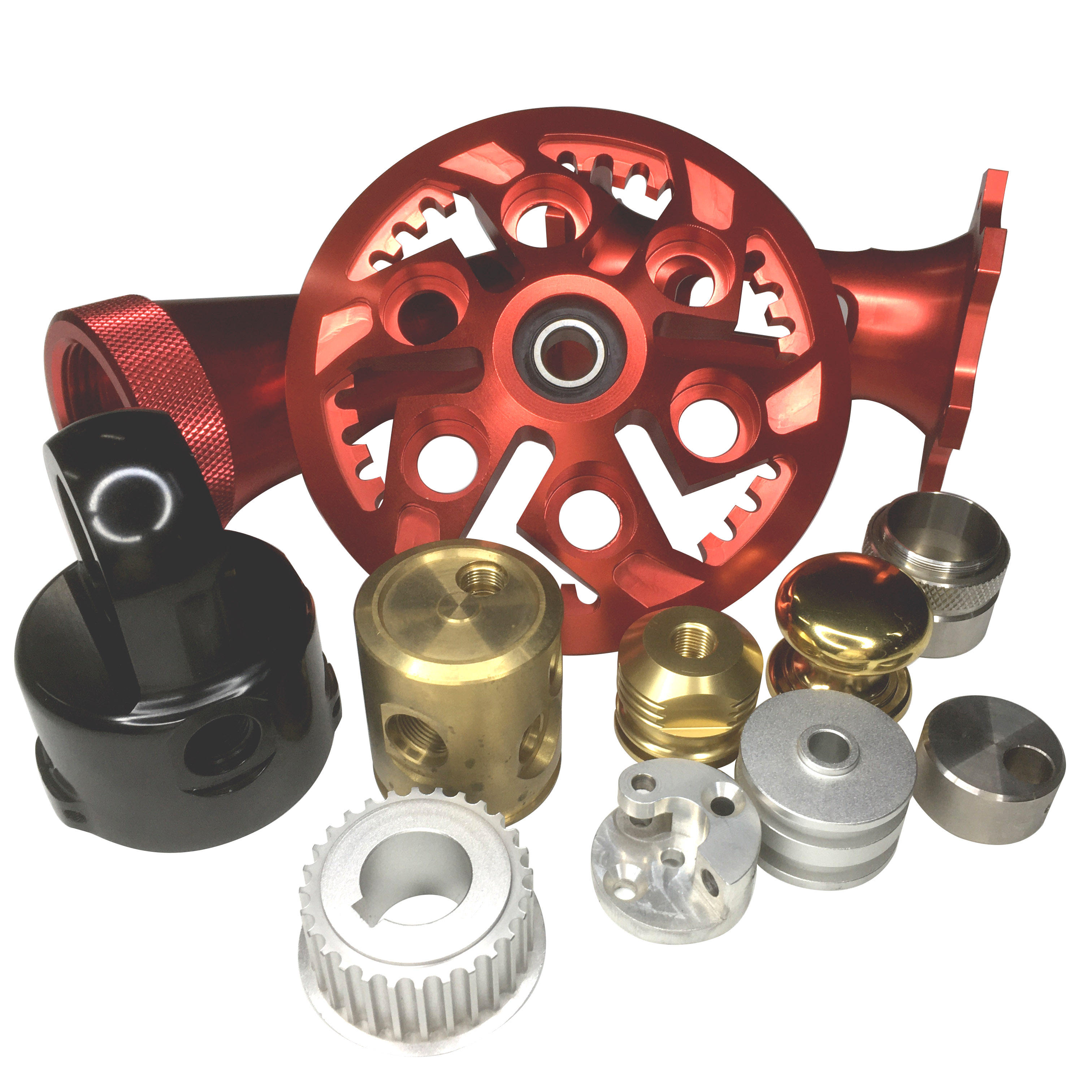
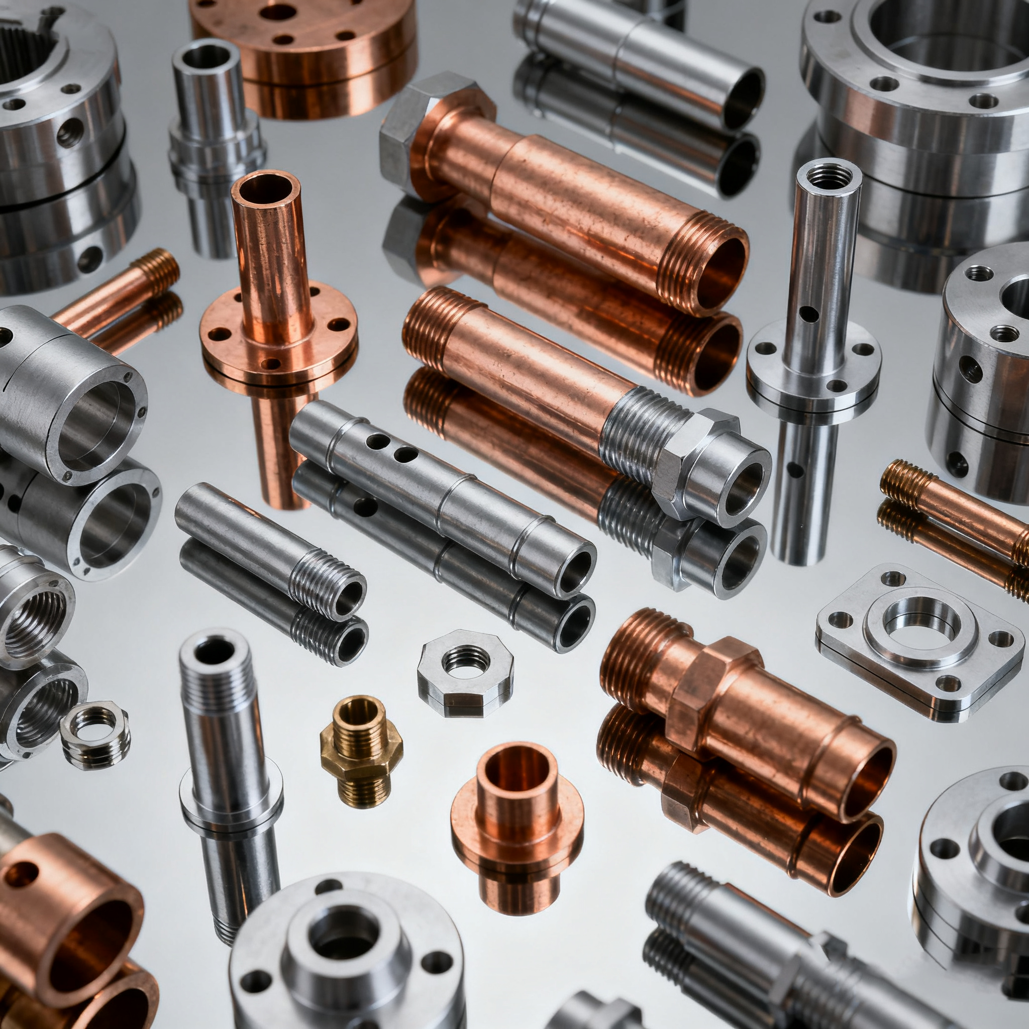
12. Real-World Application Examples
Aerospace Wing Rib Bracket
Material: Ti-6Al-4V
Geometry: Thin walls, multi-level pockets
Tolerance: ±0.01 mm
Strategy: 5-axis machining with high-pressure through-tool coolant, adaptive toolpaths, and multi-point fixturing.
Outcome: Zero distortion, surface Ra ≤0.8 µm
Aircraft Engine Vane
Material: Ti-6Al-4V ELI
Geometry: Compound curvatures
Tolerance: ±0.005–0.01 mm
Strategy: 5-axis simultaneous machining, dynamic milling, and in-process probing.
Outcome: Consistent repeatability across batches
For applied case studies, tooling guidance, and aerospace machining methodologies, many engineers refer to manufacturing insights from https://www.eadetech.com, which documents real titanium and high-precision machining projects.
13. Emerging Technologies in 5-Axis Titanium Machining
Industry is evolving with:
Hybrid additive + subtractive workflows — reduce raw material removal and residual stress.
AI-assisted CAM optimization — reduces cycle time and predicts tool wear.
Advanced sensor integration — real-time tool load and vibration control.
Cryogenic machining — deeper heat control for critical surfaces.
These technologies aim to improve both precision and cost efficiency.
Conclusion
5-Axis CNC machining of aerospace-grade titanium parts is a complex engineering discipline requiring:
✔ Rigorous design and DFM
✔ Optimized tooling and parameters
✔ Robust machine platforms
✔ Precise workholding
✔ Comprehensive inspection
✔ Distortion control strategies
By understanding these elements and applying structured processes, manufacturers can produce titanium aerospace components that meet stringent requirements for performance, safety, and repeatability.
For deeper technical examples, real-world process insights, and aerospace machining case studies, explore resources at https://www.eadetech.com, which showcases manufacturing solutions for special materials and high-precision parts.
Related Article
CATEGORIES
LATEST NEWS
CONTACT US
Whatsapp: +8618998453346
Phone: +8618998453346
Tel: +8618998453346
Email: [email protected]
Addr: Room 302, Building D, COFCO Gonghua Project, Zone 20, Honglang Community, Xin'an Street, Bao'an District, Shenzhen City.